


Setting up the hardware
Assemble the STM32 board by soldering the rows of pins supplied onto the sides and end of the board.
 to
to 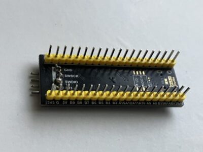
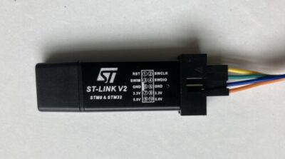
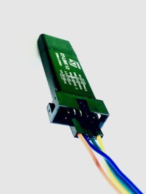
Connect the ST-LINK programmer 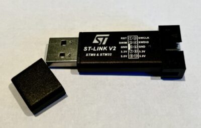 to the STM32 ARM chip
using wiring as shown:
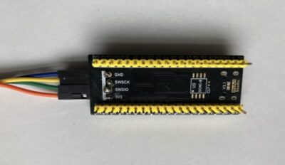
The pins are connected as shown:
- GND to GND
- SWSCK to SWSCK
- SWDIO to SWDIO
- 3V3 to 3V3
Note that the ST-Link programmer has two rows of pins – use the lower row (even-numbered pins)
Plug the ST-LINK programmer in to a USB socket on your laptop.
Loading the DIYDAQ executable onto the development board
Download the free ST-LINK development utility by visiting:
https://www.st.com/en/development-tools/stsw-link004.html
and following the instructions to install it.
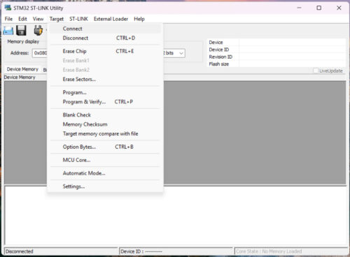
Open the ST-Link Utility by double-clicking the ST-LINK icon. ![]()
From the top menu, select Target and then Connect from the dropdown menu.
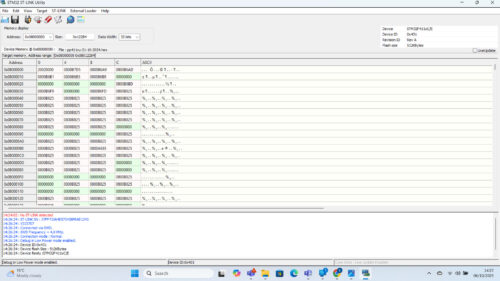
The screenshot below shows a successful connection.
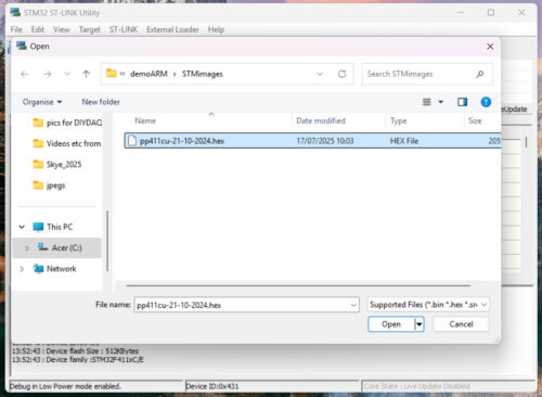
You should now open the DIYDAQ-supplied executable file by selecting File > Open file as shown below:
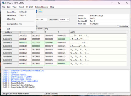
A dialogue box will appear – use this to select the executable image file.
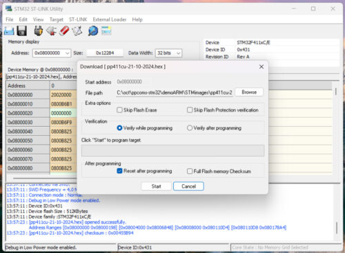
Use the Target dropdown menu to select “Program & Verify” as shown:
Download the executable file onto the chip using the dialogue and selecting “Start”.
Successful programming is shown by the screen which then appears:

You may then use Target > Disconnect and unplug the programmer.